About us
Polaxis is owned by Hanabi Sprl and is based in Belgium.
The main goal of Polaxis is to develop and sell open source electronic kits and sound machines.
VAT BE881386243
Hanabi SPRL
Rue de saint-hubert, 521 D
5300 Vezin
VAT BE881386243
Hanabi SPRL
Rue de saint-hubert, 521 D
5300 Vezin
The general terms and conditions describe and regulate the conditions for commercial transactions of and with Hanabi Sprl owner of the Polaxis webstore. In case of legal complications, legal jurisdiction is exercised in Belgium.
Kits and products from Hanabi are sold with the following terms and conditions. If you don’t understand or agree with these terms and conditions, you should not purchase or construct kits or products from Polaxis
These general conditions of sale are those in which Hanabi offers the provision of goods and services by electronic means related to the Polaxis trademark on the Polaxis website: http://polaxis.pswebshop.com
We only accept Paypal payments. Please note you can make a Paypal payment with your credit card without opening a Paypal account if you do not wish to do so.
Orders are subject to pay Belgium VAT (21%). Businesses within the EU and outside Belgium are to be invoiced ex-VAT as permitted by law by providing their VAT N°.
it is the responsibility of the buyer to pay customs charges and any applicable VAT on the import of goods into his country, as well as to ensure that the goods comply with the local laws of the importing country.
All orders are shipped from Belgium. We usually ship within 2 business days, but please allow us up to 5 business days after the payment has been received for exceptional cases.
Once the parcel has been shipped, you will receive a tracking number via email – except if the chosen shipping option does not provide any tracking information.
Average delivery time is 2-8 days within Europe, 5-15 days outside Europe. These times are indicative and do not constitute a commitment on our part.
It is the responsibility of the buyer to provide a shipping address where postal services are able to deliver the parcel. In addition, we cannot be held responsible for non-delivery if the provided shipping address cannot be served by the postal service or if the provided shipping address contains errors.
In case of a lost parcel, a minimum of 30 days must elapse before filing an appeal with the carrier. Once the loss is recorded by the carrier, we will reship the goods, except in cases of temporary or permanent unavailability of the product, in which case we will make a full refund of the order.
In compliance with the Belgium Consumer Rights Law, the private individual consumer is given a cancellation deadline of seven days from the delivery date of the order.
If you want to return your order, please contact us within 7 days of receipt of your package to obtain a return number. No return package will be accepted without this return number. We only accept returns of complete modules, unopened components bags and unsoldered PCB’s.
As part of a return you are responsible for : the cost of returning the goods as well as any damage that may occur during the return transportation (including lost package).
Belgium taxes and customs may apply if you send from a country outside the European Union.
Items sold in kit are not warranted: It is your responsibility to install the kit properly by carefully following the installation instructions found on our website. Technical support is available from our web forums.
Before buying a kit, make sure you have the skills needed for its installation, its possible debugging and maintenance.
Trademark: Polaxis is a trademark of the company Hanabi Sprl
Enterprise N°: 0881.386.243
VAT N°: BE0881386243
Address:
Rue Saint-Hubert 521d
Vezin 5300
Belgium
Packages are generally dispatched within 2 days after receipt of payment and are shipped via UPS with tracking and drop-off without signature. If you prefer delivery by UPS Extra with required signature, an additional cost will be applied, so please contact us before choosing this method. Whichever shipment choice you make, we will provide you with a link to track your package online.
Shipping fees include handling and packing fees as well as postage costs. Handling fees are fixed, whereas transport fees vary according to total weight of the shipment. We advise you to group your items in one order. We cannot group two distinct orders placed separately, and shipping fees will apply to each of them. Your package will be dispatched at your own risk, but special care is taken to protect fragile objects.
Boxes are amply sized and your items are well-protected.
Mozzi by Tim Barras is an outstanding library that allow the Arduino to produce complex and exiting sounds with almost no additional hardware.
(In fact MozMo uses the hifi mode that requires … 2 resistors and a cap !) The idea was to build a dirty cheap modular synth exploiting the vast potential of this library.


Here is one example
Check my Soundcloud for more demos

I am building a collection of Mozzi sketches adapted for this module.
(wait for the page to load as there a few Soundclouds files embedded)
You can help me to build this collection by sending me your best sketches.
All the hardware files and the Arduino sketches are kept under my Github repository
If you plan to build one, have a look a this https://www.evernote.com/l/AAUrhQ524SpHc4VzwlT0_xva_Gbh5OW4n_8
I keep a few pieces of each components and I can ship :
Here is the schematic. Nothing really special : A simple RC filter I have used before with the Talkie library and a few pots to fiddle with the various functions. All the entries (cv and gate) are now protected with diodes to allow connections with modulars synths modules using higher voltages. A simple 7 segment to show the current playing mode. I plan to use the dot as the clock led

I am ordering 8 Pcb from Beta Layout.
Here is the preview I got by uploading the file to their web site

Added female voice used in the talking clock
Here is the setup : a clock with variable pulse width is triggering the sound and stepping a sequencer feeding cv to the module. A bit of reverb is sometimes added just for fun
More demo on my Soundcloud
You can find all the files (hardware & software) on my Github
This arduino based module works thanks to a clever library : Talkie from https://github.com/going-digital/Talkie
I have already used this library to build a Talking clock
It is so simple to use that building a sound module requires only 5 pots and a button to get going.
I have slightly modified the original library to allow hacking it with various pots. The code is hosted on my github I edit the code and library directly from my favorite IDE : UECIDE

For the moment I have added 4 modes or sound banks :
I plan to add a 5th mode with a large vocabulary and a 6th mode with weird sounds
CV signal change the words or phrase to be said
Pressing the button start the complete sound in trigger mode. (regardless of it’s length)
If the trigger switch is off, the gate will start the sound and hold it as long as the gate level stays up. Very useful to create crazy rhythms.
If the cable is plugged in, the gate is triggered via an external signal
Choose between trigger mode or gated mode
If bend is on, the bend pot … distords the sound.
Change the speed
Change the pitch
First test of the differents functions. Manual gate via a button
Looping a sequence in Ableton Live to trigger gate & cv while I play with the mode /speed /pitch / bend knobs
I am now working on a PCB and a panel.
I will upload these details and the schematics in a next post.
As you can read on the Wikipedia page, the SSI-263 is the other name for the Votrax SC-02.
It is becoming quite difficult to find, much harder then it’s little brother the Votrax SC-01 but I finally got one by buying a Mockingboard B on Ebay.
The SSI-263 is TTL compatible and need only very few component to be added. It is very easy to connect it to an Arduino but is much more complex than the Votrax-SC01 to program.
As I planned to make many software iteration and process the text to speech routine from Python, I decided to use Nanpy on the Arduino to « relay » the instructions to the chip. I guess I could also use Firmata to do the job as I am using really basics stuff like writing bytes on various pins.
The SSI-263 datasheet is quite easy to find and so the programming guide via some Google search but the best one I found is the Votrax SC-02 version that has an extra page at the end with a nice and very simple schematics to get started with .
As I plan to build a shield for the Arduino, I started to draw this in Eagle too :
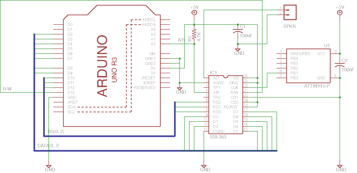
You can download the Eagle version here
The chip needs a 1-2 MHz clock signal. I am using a Attiny 45 to do the job because all the timer pins are already in use on the Arduino. I have described how to use the Attiny45 to do this in a previous post
The best reference to get started is the article from Steve Ciarca : “Build a Third-Generation Phonetic Speech Synthesizer ».
A complete version is available on Google books. Ciarcia, Steve, “Build a Third-Generation Phonetic Speech Synthesizer,” Byte, March, 1984, p 28. (SSI-263)
There is also a reference to the SSI-263 and to many other speaking chip in “Chip Talk: Projects in Speech Synthesis” but the chapter mainly refers to Steve’s article.
The book is still available in some second hand book shop (I got mine via Amazon). The information provided is minimal but it’s fun to ready about all these veterans speaking chips.
Prochnow, Dave, Chip Talk: Projects in Speech Synthesis, Tab Books, Blue Ridge Summit, PA: 1987. ISBN is 0-8306-1912-7 (hard cover) and 0-8306-2812-6 (paperback).
Have also a look here : http://www.redcedar.com/sc01.htm. The page is regularly updated and makes an excellent starting point.
Here is the Main code
The text-to speech is performed via a lookup in the CMU Dictionary (The dictionary can be install with these instructions : http://stackoverflow.com/questions/11911028/python-arpabet-phonetic-transcription)
It return an arpabet version of the text which is then translated into the Votrax allophone table.
(thank to this modified Arpabet to unicode script)
The allophone chain is then sent to the chip
The code is very basic and doesn’t use the SSI263 registers to their full potential : the voice generated is very robotic … but I like it a lot
Listen to the chip saying the Issac Assimov’s 3 laws of robotics with 2 different voice settings :
Next thing I will try is to add prosody or even make it sing
On the hardware side I plan to add a RC filter with an amplifier and add a midi in to the circuit .. so stay tuned.
Clock
Wiring
Talkie
I’ve discovered this great library here https://github.com/going-digital/Talkie
They have done an impressive job. The library is provided with a large vocabulary.
It is a software implementation of the Texas Instruments speech synthesis architecture (Linear Predictive Coding). It is just amazing to discover what the atmega168 can do. By the way the library works only with 168 and 328 16MHz based Arduino.
Audio
Just for fun to hear the script counting …
And then the clock saying the time
Hardware
To build this clock you need :

I plan to add and infrared detector to allow the system to say the time by just waving a hand in the dark.
Code
I have mixed the example code provided in the talkie library to process and say numbers (Volmeter) and the vocabulary from the Vocab_US-Clock example.
The sketch wait for the button to be pressed and then read the clock’s time.
It first greet the listener for the moment of the day (morning,afternoon, evening) and then say the time
The idea
I got this brilliant idea by John Loadsman who is using a version of my previous code: http://www.youtube.com/watch?v=tUbTZU_FCz0&feature=context-cha
I also wanted to digitally control the Votrax’s pitch to implement some new functions. (keep in mind that I want the Votrax to sing)
The hardware modification was pretty easy: I removed the analog clocking part, tied the MCRC to the ground and just pulled the Votrax’s clock entry MCX to +5v with a 2.2k resistor.
I had to use pin 3 on the Arduino to produce the clock via the timer 2 and, therefore, need to use pin 6 for the A/R
Code
What’s new
– Moved the A/R to pin 6
– Using pin 3 to generate the clock (see setup section)
– Created a function to drive the clock on demand. See ClockFrequency() where the clock frequency is given in kHz.
– note: My Votrax doesn’t seem to accept a frequency bigger than 910 kHz
– Added some new modifier _PITCHUP & _PITCHDN to allow variation within the text
Todo :
– find a way to produce musical notes
– Add midi control
/* Votrax SC-O1A Speech Chip
 Sing n' Speech Processor
 Arduino Uno
 Updated to use timer to generate the clock (an excellent idea by John Loadsman (August 2012)

Changes (03/10/2012)

- Moved the A/R to pin 6
- Using pin 3 to generate the clock (see setup section)
- Created a function to drive the clock on demand (see ClockFrequency() where the clock frequency is given in kHz)
- Added some new modifier _PITCHUP & _PITCHDN to allow variation within the text


 **********************************************************************
         ___   ___
 Vp   1 |*  \_/   | 28  A0
 I2   2 |         | 21  AF
 I1   3 |         | 20  CB
 NC   4 |         | 19  NC
 TP3  5 | Votrax  | 18  Vg
 TP2  6 | SC-01 A | 17  TP1
 STB  7 |         | 16  MCRC
 A/R  8 |         | 15  MCX
 P5   9 |         | 14  P0
 P4  10 |         | 13  P1
 P3  11 |_________| 12  P2

 **********************************************************************
 */

int sensorPin = A5; // Manuel speed setting via potentiometer as voltage divider on pin 5

#define PIN_STB 2  // Strobe need to go high to latch datas
#define PIN_AR 6   // Acknowledge/Request goes high when ready (was 3)
#define PIN_I1 5   // Inflection bit1 (votrax pin 3)
#define PIN_I2 4   // Inflection bit2 (vot pin 2)

#define PIN_TIMING 7 // read the switch's status


// define all the phonemes

#define _EH3 0x00 // 59 MS ;JACKET
#define _EH2 0x01 // 71 MS ;ENLIST
#define _EH1 0x02 // 121MS ;HEAVY
#define _PA0 0x03 // 47 MS ;NO SOUND
#define _DT 0x04 // 47 MS ;BUTTER
#define _A2 0x05 // 71 MS ;MADE
#define _A1 0x06 // 103MS ;MADE
#define _ZH  0x07 // 90 MS ;AZURE
#define _AH2 0x08 // 71 MS ;HONEST -
#define _I3  0x09 // 55 MS ;INHIBIT
#define _I2  0x0A // 80 MS ;INHIBIT
#define _I1  0x0B // 121MS ;INHIBIT
#define _M  0x0C // 103MS ;MAT
#define _N  0x0D // 80 MS ;SUN
#define _B  0x0E // 71 MS ;BAG
#define _V  0x0F // 71 MS ;VAN
#define _CH  0x10 // 71 MS ;CHIP
#define _SH  0x11 // 121MS ;SHOP
#define _Z  0x12 // 71 MS ;ZOO
#define _AW1 0x13 // 146MS ;LAWFUL
#define _NG  0x14 // 121MS ;THING
#define _AH1 0x15 // 146MS ;FATHER
#define _OO1 0x16 // 103MS ;LOOKING
#define _OO  0x17 // 185MS ;BOOK
#define _L  0x18 // 103MS ;LAND
#define _K  0x19 // 80 MS ;TRICK
#define _J  0x1A // 47 MS ;JUDGE
#define _H  0x1B // 71 MS ;HELLO
#define _G  0x1C // 71 MS ;GET
#define _F  0x1D // 103MS ;FAST
#define _D  0x1E // 55 MS ;PAID
#define _S  0x1F // 90 MS ;PASS
#define _A  0x20 // 185MS ;DAY
#define _AY  0x21 // 65 MS ;DAY
#define _Y1  0x22 // 80 MS ;YARD
#define _UH3 0x23 // 47 MS ;MISSION
#define _AH  0x24 // 250MS ;MOP
#define _P  0x25 // 103MS ;PAST
#define _O  0x26 // 185MS ;COLD
#define _I  0x27 // 185MS ;PIN
#define _U  0x28 // 185MS ;MOVE
#define _Y  0x29 // 103MS ;ANY
#define _T  0x2A // 71 MS ;TAP
#define _R  0x2B // 90 MS ;RED
#define _E  0x2C // 185MS ;MEET
#define _W  0x2D // 80 MS ;WIN
#define _AE  0x2E // 185MS ;DAD
#define _AE1 0x2F // 103MS ;AFTER
#define _AW2 0x30 // 90 MS ;SALTY
#define _UH2 0x31 // 71 MS ;ABOUT
#define _UH1 0x32 // 103MS ;UNCLE
#define _UH  0x33 // 185MS ;CUP
#define _O2  0x34 // 80 MS ;FOR
#define _O1  0x35 // 121MS ;ABOARD
#define _IU  0x36 // 59 MS ;YOU
#define _U1  0x37 // 90 MS ;YOU
#define _THV 0x38 // 80 MS ;THE
#define _TH  0x39 // 71 MS ;THIN
#define _ER  0x3A // 146MS ;BIRD
#define _EH  0x3B // 185MS ;GET
#define _E1  0x3C // 121MS ;BE
#define _AW  0x3D // 250MS ;CALL
#define _PA1 0x3E // 185MS ;NO SOUND
#define _STOP 0x3F // 47 MS ;NO SOUND

#define _END 99  // End of phrase

#define _INFL0   100 // Inflection 0 (default mode)
#define _INFL1   101 // Inflection 1
#define _INFL2   102 // Inflection 2
#define _INFL3   103 // Inflection 3
#define _HOLD1   200 // wait 300 ms
#define _HOLD2   201 // wait 600 ms
#define _PITCHDN 202 // get pitch down
#define _PITCHUP 203 // get pitch up


void ClockFrequency(float freq)
{
  long topv = (long) ((float) F_CPU /(freq*1000 ));
  OCR2A =  (int)((float) topv)-1;

 }


void setup()
{

  DDRB = B00111111; // set Port B 6 lowest bit as Output (Arduino Uno pin 8 to 13)

  pinMode(PIN_TIMING,INPUT);

  pinMode(PIN_STB, OUTPUT);
  pinMode(PIN_AR, INPUT);

  pinMode(PIN_I1, OUTPUT);
  pinMode(PIN_I2, OUTPUT);

  digitalWrite(PIN_I1, LOW);  // default to no inflection
  digitalWrite(PIN_I2, LOW);  // default to no inflection

  digitalWrite(PIN_STB, LOW);   // must stay low

  // PWM outputs via timer 2 (Arduino uno digital pin 3)

  pinMode(3, OUTPUT);       // enable the PWM output
  TCCR2A = B00100011;      // Fast PWM change at OCR2
  TCCR2B = B11001;         // Timer running at full system clock
  OCR2A = 21;              //  output frequency = 16,000,000/(OCR5A+1)    21 ==> 727272 Hz, 18 ==> 842105 Hz
  pinMode(3, OUTPUT);      // enable the PWM output (you now have a PWM signal on digital pin 3)
  OCR2B = 11;              // 50% duty cycle


}


void loop()
{

  ClockFrequency(600);

  byte radioactive[]={
    _INFL2,
    _T,_CH,_ER,_HOLD1,_N,_O,_HOLD1,_B,_INFL3,_I,_HOLD1,_L,_PA1,_HOLD1,_INFL1,                                                            // Tchernobyl
    _H,_A1,_HOLD1,_R,_E,_HOLD1,_S,_B,_ER,_HOLD1,_G,_HOLD1,                                                                               // Harrisburg
    _S,_EH1,_HOLD1,_L,_AH2,_HOLD1,_F,_INFL2,_E,_HOLD1,_L,_D,_PA1,_INFL2,_HOLD1,                                                          // Sellafield
    _F,_PITCHDN,_U,_HOLD2,_K,_PITCHDN,_U,_HOLD2,_SH,_PITCHDN,_E,_HOLD2,_M,_INFL0,_PITCHUP,_PITCHUP,_PITCHUP,_PITCHUP,_AW2,_HOLD2,_HOLD2, // Fukushima
    _STOP  };

 speak (radioactive);

 ClockFrequency(730);

  byte votrax[]={

    _INFL0,
    _V,_O,_T,_R,_UH,_K,_S,_PA1,                        // Votrax
    _INFL1,_EH1, _EH2, _S,_PA0,                        // S
    _S, _E1, _Y,_PA0,                                  // C
    _Z,_AY,_I1,_R,_O1,_U1,_PA0,                        // Zero
    _W,_UH1,_UH2,_N,_PA0,                              // One
    _A,_AY,_Y,_PA1,_INFL2,                             // A
    _S,_P,_E1,_Y,_T,_CH,_PA0,                          // Speech
    _S,_I,_N,_T,_EH2,_S, _AH1,_E1,_Z,_ER,_PA0,_INFL3,  // Synthesizer
    _R, _EH1, _EH3, _D, _Y,_STOP  };                   // Ready

  // speak (votrax);

   byte dalek7[]={_INFL2, 0x38,0x33,0x03,_INFL3,0x1e,0x24,0x18,_INFL2,0x02,0x19,0x1f,0x15,0x15,0x2b,0x38,0x33,0x1f,0x36,0x25,0x27,0x2b,0x22,_PITCHDN,0x3a,0x0e,0x2c,0x0b,0x14, 0x3e,_PA1,_HOLD2,0x3f};
  //"The Daleks are the superior being."
  speak (dalek7);


  byte inflection[]={
    _INFL0,_V,_O,_T,_R,_UH,_K,_S,_PA1,          // Votrax
    _INFL1,_V,_O,_T,_R,_UH,_K,_S,_PA1,
    _INFL2,_V,_O,_T,_R,_UH,_K,_S,_PA1,
    _INFL3,_V,_O,_T,_R,_UH,_K,_S,_PA1,
    _STOP  };

    ClockFrequency(910);
    speak (inflection);


  delay(2000); // delay 2 sec between repetition

}


void speak (byte* message){

  int i=0;
  do
  {
    say(message[i]);
    i++;

  }
  while (message[i-1]!=_STOP);

}


void say(byte phoneme) {

  if (digitalRead(PIN_TIMING) ==1) {          // Read the switch's status
    //  Wait for PIN_AR=1 when chip is ready : internal timing
    while (digitalRead(PIN_AR) == 0);
  }
  else                                       // if switch is low get timing via pot's value
  {
    int sensorValue = analogRead(sensorPin);
    int sustain = map (sensorValue,0,1023,40,300);
    delay(sustain);
  }
  switch (phoneme) {
  case _INFL0:
    digitalWrite(PIN_I1, LOW);
    digitalWrite(PIN_I2, LOW);
    break;

  case _INFL1:
    digitalWrite(PIN_I1, HIGH);
    digitalWrite(PIN_I2, LOW);
    break;

  case _INFL2:
    digitalWrite(PIN_I1, LOW);
    digitalWrite(PIN_I2, HIGH);
    break;

  case _INFL3:
    digitalWrite(PIN_I1, HIGH);
    digitalWrite(PIN_I2, HIGH);
    break;

  case _HOLD1:
    delay (300);
    break;

  case _HOLD2:
    delay (600);
    break;

  case _PITCHDN:
  OCR2A=OCR2A+4;
  break;

  case _PITCHUP:
  OCR2A=OCR2A-4;
  break;

  default:
    PORTB =  phoneme;


    // Set PIN_STB = 1 for 2usec to tell the chip to read the Port
    digitalWrite(PIN_STB, HIGH);
    delayMicroseconds(2);
    digitalWrite(PIN_STB, LOW);


  }
}
Audio